
Technical guide to assembling HP server parts
Assembling an HPE ProLiant or Apollo server is not merely a matter of plugging components in; it’s a precision engineering process critical to achieving peak throughput and minimal latency. Misconfiguration or component incompatibility, even in one part, can throttle the entire system’s efficiency. This technical guide outlines the essential steps and best practices for installing the core internal components—CPU, RAM, and Storage—in modern HPE server generations (Gen10/Gen11).
Pre-Installation Checklist & System Preparation
Before commencing hardware installation, adherence to strict protocol is paramount to prevent electrostatic discharge (ESD) and ensure physical compatibility.
- ESD Precautions: Always wear an anti-static wrist strap connected to a grounded point on the chassis. Perform all work on an anti-static mat.
- Documentation Check: Consult the HPE Server User Guide (e.g., for DL380 Gen11) for the specific system board layout, DIMM slot numbering, and supported processor TDP limits.
- Firmware Baseline: Ensure the System ROM (BIOS) and iLO firmware are updated to a compatible baseline before introducing new generation components, especially high-speed memory or NVMe drives.
Central Processing Unit (CPU) Installation
The CPU determines the server’s compute capacity and memory bus speed, making its installation the most delicate and critical step.
1. Thermal and Socket Preparation
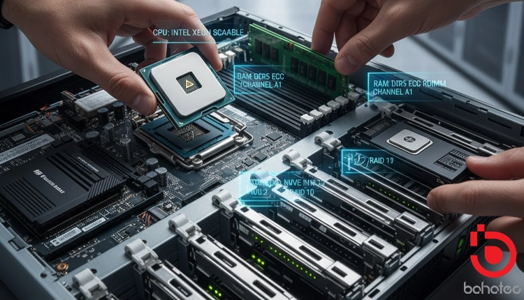
The processor type (Intel Xeon Scalable or AMD EPYC) dictates the socket type (LGA 4189, LGA 4677, or SP3/SP5).
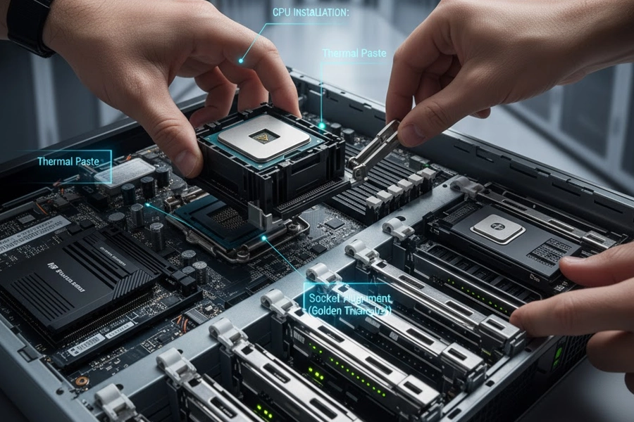
- Heatsink Carrier: For modern HPE servers, the CPU is often installed into a Processor and Heatsink Module (PHM) first. This ensures perfect alignment and optimal thermal contact.
- Thermal Paste Application: If re-using a heatsink (not recommended for max performance builds), thoroughly clean the residual paste. Apply a thin, uniform layer of high-quality thermal interface material (TIM) to the center of the CPU integrated heat spreader (IHS). HPE often provides CPUs pre-installed in a carrier with thermal grease pre-applied to the heatsink.
- Alignment: Align the golden triangle/arrow on the CPU with the corresponding mark on the socket carrier or the motherboard socket. Lower the CPU gently and without force.
2. Securing the Module
- PHM Installation: Place the assembled PHM onto the socket. Secure the retaining mechanism (usually a lever or two captive screws) in the sequence indicated on the heatsink (often 1 $\rightarrow$ 2) to ensure even pressure distribution and maximum thermal transfer.
- High-TDP Considerations: For CPUs with a high Thermal Design Power (TDP), such as those exceeding 250W, verify that High-Performance Fan Kits are installed and that the correct heatsink model is used, as base models often only support Standard TDP parts.
Random Access Memory (RAM) Configuration
HPE servers utilize ECC Registered DIMMs (RDIMMs) or Load-Reduced DIMMs (LRDIMMs). Achieving maximum memory bandwidth requires strict adherence to the Channel Rule and population order.
1. DIMM Selection and Speed Matching
- ECC Requirement: Only HPE SmartMemory (ECC) is certified and ensures optimal reliability.
- Maximum Speed: The memory speed (e.g., DDR4-3200 MT/s or DDR5-4800 MT/s) is capped by the lowest common denominator among the CPU’s memory controller, the DIMM speed, and the number of ranks populated per channel. Always match the highest supported speed of the processor.
- Population Strategy (Channel Rule): HPE systems employ a multi-channel architecture (typically 6 or 8 channels per CPU). Memory modules must be populated in matched pairs, triples, or quadruples across the channels to enable Interleaving and Multi-Channel Mode, which significantly increases bandwidth.
2. Installation Procedure
- Reference the DIMM Slot Map: Crucially, always follow the DIMM Slot Map printed on the server’s access panel or air baffle. Slots are usually numbered A1, B1, C1, etc.
- Installation Order: Start with the primary slot of the first channel (e.g., Slot 1 or 1A) and populate outward, ensuring symmetrical distribution across all available channels for each processor.
- Seating: Open the ejector clips, align the module keyway with the slot notch, press down firmly and evenly on both ends until the clips snap shut. Do not force the module.
Storage Subsystem Integration
Storage choice affects IOPS (Input/Output Operations Per Second) and latency. The installation involves drive carriers and the RAID controller.

1. Drive Installation (Caddies)
- Drive Type: Differentiate between SAS/SATA (Hot-Plug LFF/SFF) and NVMe U.2/U.3 drives. NVMe drives often require dedicated backplanes and optional NVMe Riser Cards.
- Drive Caddies: Install the chosen drive (HDD, SATA/SAS SSD, or NVMe) into the corresponding HPE Smart Carrier or NVMe carrier.
- Insertion: Insert the caddy into the appropriate front bay slot. A solid green status LED confirms proper seating and connectivity.
2. RAID Controller and Connectivity
- Smart Array Controller: Most HPE systems use a Smart Array Controller (e.g., P408i or P816i) for SAS/SATA RAID. Confirm the controller supports the required disk protocols (12G SAS, 24G SAS, or SATA).
- RAID Configuration: After initial boot, the RAID arrays must be configured using the HPE Smart Storage Administrator (SSA), accessible via Intelligent Provisioning (iLO).
- RAID 10: Recommended for high-performance databases, prioritizing speed and two-disk fault tolerance.
- RAID 6: Recommended for high-capacity archives where maximum capacity and tolerance for two simultaneous disk failures are necessary.
- NVMe Drive Integration: NVMe drives bypass the traditional RAID controller, often connecting directly via PCIe lanes. In this scenario, Intel VROC (Virtual RAID on CPU) is typically used for basic NVMe RAID configurations, managed outside the traditional SSA interface.
Riser Cards and I/O Connectivity
PCIe Riser Cards allow for expansion with networking cards, GPUs, or additional controllers.
- Riser Card Seating: Riser cages must be seated firmly into their dedicated connectors on the motherboard. Incorrect seating is a common cause of boot failures.
- Networking: Install HPE Ethernet or Fibre Channel adapters (NICs/HBAs) into the PCIe slots as per the slot map to ensure the desired bandwidth (e.g., 25GbE, 100GbE) is achieved. Pay attention to PCIe generation (Gen4 vs. Gen5) and lane width (x8 vs. x16) to avoid I/O bottlenecks.
Final Checks and Power-Up
- Cable Management: Ensure all internal cables (power, data, fan cables) are routed neatly and secured with Velcro straps to prevent obstruction of the airflow. Poor cable management is a common cause of overheating.
- Airflow Baffle: Re-install the airflow baffle (plastic or metal cover over the CPU/RAM) and the top access panel. This component is essential for directing cooling air to the critical components.
- Initial Boot: Connect power and network cables, power on the server, and enter the iLO interface. Verify that the System Health LED is green and check the I/O Summary within iLO to confirm that all installed components (CPU, DIMMs, Controllers, NVMe drives) are correctly detected and operating at their negotiated speeds.
Bahatec: Your Dubai Partner for Optimized HPE Server Solutions
Looking for peak server performance in Dubai? Bahatec specializes in the expert selection, optimal assembly, and supply of genuine HPE server components. We don’t just sell parts; we engineer your solution.
Our technical team ensures every component—from high-TDP CPUs and multi-channel RAM to NVMe storage and RAID controllers—is chosen and assembled to maximize throughput and eliminate performance bottlenecks. Trust Bahatec for reliable, precisely configured HPE servers tailored to your mission-critical workloads. Maximize your IT investment with our performance guarantee.